pembelajaran tanpa batas www.malang-center.blogspot.com

  • RSS
  • Delicious
  • Digg
  • Facebook
  • Twitter
  • Linkedin
Sit amet felis. Mauris semper,

Welcome to WordPress. This is your first post. Edit or delete it, then start blogging!Lorem ipsum dolor sit amet, consectetuer adipiscing elit. Quisque sed felis. Aliquam sit amet felis. Mauris semper, velit semper laoreet dictum, quam diam dictum urna, nec placerat elit nisl in quam. Etiam augue pede, molestie eget, ...

Category name clash

Lorem ipsum dolor sit amet, consectetuer adipiscing elit. Quisque sed felis. Aliquam sit amet felis. Mauris semper, velit semper laoreet dictum, quam diam dictum urna, nec placerat elit nisl in quam. Etiam augue pede, molestie eget, rhoncus at, convallis ut, eros. Aliquam pharetra. Nulla in tellus eget odio sagittis blandit. ...

Test with enclosures

Here's an mp3 file that was uploaded as an attachment: Juan Manuel Fangio by Yue And here's a link to an external mp3 file: Acclimate by General Fuzz Both are CC licensed. Lorem ipsum dolor sit amet, consectetuer adipiscing elit. Quisque sed felis. Aliquam sit amet felis. Mauris semper, velit semper laoreet dictum, ...

Block quotes

Some block quote tests: Here's a one line quote. This part isn't quoted. Here's a much longer quote: Lorem ipsum dolor sit amet, consectetuer adipiscing elit. In dapibus. In pretium pede. Donec molestie facilisis ante. Ut a turpis ut ipsum pellentesque tincidunt. Morbi blandit sapien in mauris. Nulla lectus lorem, varius aliquet, ...

Contributor post, approved

I'm just a lowly contributor. My posts must be approved by the editor.Mauris semper, velit semper laoreet dictum, quam diam dictum urna, nec placerat elit nisl in quam. Etiam augue pede, molestie eget, rhoncus at, convallis ut, eros. Aliquam pharetra. Nulla in tellus eget odio sagittis blandit. Maecenas at ...

Showing posts with label Rangkaian Elektronik. Show all posts
Posted by Ezkajivo - - 1 comments

although this adapter is very simple but this circuit is stable and can be used for voltages up to 37volt (by changing the value of R).

Fout is minimal 1.25volt if you require a higher power, can ic 5A replaced by LM338, LM350 3A, or also by adding external transistors cross I use it on some equipment.

Adaptor variabel LM317

Skema Rangkaian Adaptor variabel 3.7 volt - 37 Volt


stability of this LM317 slightly better than the 78xx class because it was used as the feedback output is not only a reference voltage (78xx kls can also be used as adjustable by lifting the voltage reference terminal wrote in the ground).
resistance value of the above is not ideal but I used to value used, to the ideal of R can be larger because the feedback terminal below only requires 1mA current.


Abaot IC LM317

The LM117 series of adjustable 3-terminal positive voltage regulators is capable of supplying in excess of 1.5A over a 1.2V to 37V output range. They are exceptionally easy to use and require only two external resistors to set the output voltage. Further, both line and load regulation are better than standard fixed regulators. Also, the LM117 is packaged in standard transistor packages which are easily mounted and handled.


Features IC LM317

• Guaranteed 1% output voltage tolerance (LM317A)
• Guaranteed max. 0.01%/V line regulation (LM317A)
• Guaranteed max. 0.3% load regulation (LM117)
• Guaranteed 1.5A output current
• Adjustable output down to 1.2V
• Current limit constant with temperature
• P + Product Enhancement tested
• 80 dB ripple rejection
• Output is short-circuit protected.
[ Read More ]

Posted by Ezkajivo - - 1 comments

FET is divided into two families: Junction FET (JFET) and Insulated Gate FET (IGFET) or also known as Metal Oxide Silicon (or semiconductor) FET (MOSFET). In contrast to the IGFET, the JFET gate terminal forming a diode with the channel (semiconductor material between the Source and Drain). In its function, this makes N-channel JFET to be a solid-state version of the vacuum tubes, which also forms a diode between the grid and cathode. And also, both (JFET and vacuum tubes) work in "depletion mode", both have a high input impedance, and they conduct electrical current under the control of the input voltage.

Mengukur  Kerusakan Fet Dengan Multimeter
Mengukur Kerusakan Fet Dengan Multimeter


Determination of FET performed by investigators x100 range of black and red on the Source Gate. When the needle to deviate, then the FET is kanalP Janis and if not, the FET is the channel N.

Damage to the FET can be observed with a series of pictures. Range is placed on x1k or x10k, potensio at a minimum, the resistance should be small. When potensio rotated to the right, the resistance should be infinite. If this does not happen, then the possibility of FET damaged.
[ Read More ]

Posted by Ezkajivo - - 0 comments


This circuit, connected to the loudspeaker output of an audio amplifier, will indicate the instantaneous output power delivered to the loudspeaker(s) by means of six LEDs illuminating one after another by voltage values increasing little by little, providing the visual impression of a luminous bar or column, increasing and decreasing in height following the increase and decrease of the signal’s level.


Rangkaian Indicator Daya Audio AmplifierSkema Rangkaian Indicator Daya Audio Amplifier


Notes:
  • The output power indicated by each LED must be doubled when 4 Ohms loads are driven.
  • The circuit can be adapted to suit less powerful amplifiers by reducing the number of LEDs and related voltage dividers.


List Component :

R1: 220R 1/2W Resistor
R2,R5,R6,R8: 100R 1/4W Resistors
R10,R12,R14: 100R 1/4W Resistors
R3: 220R 1/4W Resistor
R4,R7: 330R 1/2W Resistors
R9: 560R 1/2W Resistor
R11: 820R 1/2W Resistor
R13: 1K2 1/2W Resistor

D1: 1N4004 400V 1A Diode
D2,D4,D6: BZX79C2V7 2.7V 500mW Zener Diodes
D3,D5,D7,D8,D9,D10 Red LEDs (Any dimension and shape) (See Notes)


The input signal is first rectified by D1 and then sent to six different voltage dividers, one for each LED. In this way, the indication provided by the LEDs illumination of this “Power Display”, will be related to the instantaneous power sunk by the whole loudspeaker cabinet.
Six output power levels are displayed by the LEDs in a 2W - 80W range (no setup required). Each nominal power level indication into 8 Ohms load is reached when the respective LED illuminates at full brightness.
[ Read More ]

Posted by Ezkajivo - - 2 comments

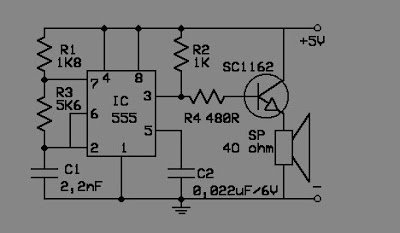
Mice are wild animals and very annoying. "Action bawdy" it could be all kinds ranging from pooping everywhere, rummaging through closets and warehouses, spread diseases (plague), and so on. Just always make a scene! One alternative to overcome this is to use an electronic mouse repellent. In addition to environmentally friendly, this tool can also be used as a hobby and learning the distribution of electronics.

To drive these rats disorders, you can create an electronic circuit as shown below. This circuit will generate a 50Khz frequency disturbing enough for a mouse but you do not have worried because you will not hear it. This series is guaranteed by the rats would run because his ears will feel pain from the vibration signal ferkuensi.

http://elektroarea.blogspot.com/
Skema Rangkain Pengusir Tikus


Electronic components on the need to build a mouse repellent electronic circuit is not much, quite cheap and readily available at electronics stores. Electronic circuit scheme can be viewed directly on the image above. The circuit can be built on a dot matrix or PCB layout to make it with plain munggunakan PCB. Within a few days after the installation of this device (a continuous) will be visible results. The mouse and his relatives would be taken off some where and rumahpun rid of most annoying animals.


Heart of electronic rat repellent circuit IC 555 is already very popular, cheap and versatile. For maximum results use the loudspeaker from the PIEZO tweeter speakers electric or funnel shape. Electronic rat repellent is effective for rooms up to 200 m 2 area from the right placement. This circuit is placed in the corner of the room so that his frequency noise can be spread across the room without a hitch. Turn on continuously to keep the rats do not come back, do not worry about the electricity consumption for electrical power needed is low enough, is still greater watt/220 light bulb 5 volts.
[ Read More ]

Posted by Ezkajivo - - 0 comments

The following circuit of special functions to detect the presence or absence of signal AF / RF. This circuit is very simple so as to make it requires a relatively low cost. Detektor Signal AF/RF circuit based an audio amplifier and a loudspeaker with a switch input to the AF and RF signal. The whole device can be made as small as possible so that it can be included in a container to keep the peace.

Audio amplifier section in this series created by IC TDA 2822M, with a low-power stereo amplifier in 8-pin mini-DIP. This IC is used as a bridge cofiguration to minimize output power up to 250 mW, the loudspeaker is in use 4 ohm, 500mW. Current required is less than 10mA with a 3V battery voltage.

Rangkaian Detektor Signal  AF/RF
Skema Rangkaian Detektor Signal AF/RF

List Component

R1 : 22K
R2, 3, 4 : 4K7
C1 : 1n
C2, 6, 7 : 0,1uF
C3, 4 : 10uF/16V
C5 : 0,01uf
D1 : OA79
VR1 : 22K
IC 1 : TDA2822M
LS : 8 ohm 500mW


When the switch in the AF position, Signal input audio input working on AF amplifier (IC 1 pin 7) via a capacitor C2 and Potentiometer VR1. Capacitor C2 is always holding the input amplifier of the DC voltage and make it happen in the audio signal frequency. Input signal IC 1 can be arranged with the help of potentiometer VR1.

When switch on the RF position, the detector and demodulator circuit formed by capacitor C1, diode D1, and resistors R1 and R2 are connected to the input rangakaian. When the audio signal is detected it will be significantly strengthened in kerangkaian for. Signal detection is done by plugging in tactile (probe) on the legs of the existing components.
[ Read More ]

Posted by Ezkajivo - - 0 comments

This series consists of 10 led a mounted sequential, Supply 9V IC1A needed to strengthen to 100 times and move the audio signal IC1B. Sensitivity level of the circuit can be adjusted by changing the value of R4. The value of C4 was changed from 220 to 470nF. Each input R9 must be linked with the IC2 output pins.


 Lampu LED Disko

Skema Rangkain Lampu LED Disko


Component List

R1 :10K 1/4W
R2, 3 : 47K 1/4W
R4 : 1K 1/4W
R5, 6, 7 : 100K 1/4W
R8 : 820R 1/4
C1, 3 : 100nF
C2 : 10uF/50V
C4 : 330nF
C5 : 100uF/25V
D1 : 1N4148
D2-D11 : 5 or 3mm LED
IC1 : LM358
IC2 : 4017
MIC1 : Miniature electret microphone
R9, 10 : 10K 1/4W
R11 : 56R 1/4W
D12,13 etc : 5 or 3mm LED
Q1,2 : BC327
Q3 : BC337


IC Decoder 4017

The 4017 is an extremely useful device for project work and is used in the Games Timer and in various DOCTRONICS construction kits including the Light Chaser and the Matrix Die. When you are familiar with the 4017, you will be able to think of lots of useful applications.


Internally, the 4017 contains five bistable subunits. These are interconnected in a pattern known as a Johnson counter. The outputs of the bistables are decoded to give the ten individvual outputs.
[ Read More ]